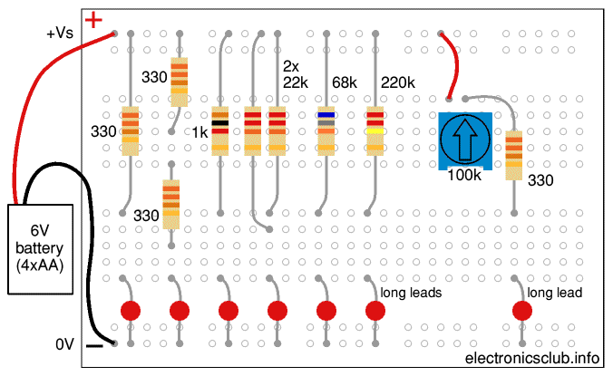
Breadboard Layout for Investigating LED Brightness:

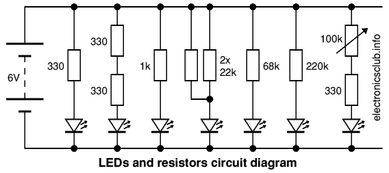
Circuit Diagram:


These projects investigate LED brightness and Pulse Width Modulation.
Projects: Investigating LED Brightness | Pulse Width Modulation | RGB LED with PWM | parts
Also see: Breadboard | 555 Astable | Counting Circuits | RGB LEDs
Next page: Breadboard Workshops
Breadboard Workshop 3 showed a RGB LED producing 8 colours by switching its internal LEDs on and off. Many more colours are possible if the brightness of each internal LED is varied.
This project investigates how the brightness of an LED might be varied with resistors (use identical LEDs for meaningful results). It also shows how resistors can be combined in series and parallel to make other values, this can be useful when experimenting if the right value isn't immediately available.
Try each resistance as shown from left to right on the breadboard and circuit diagram. Start with 330Ω as that gives maximum brightness without risking damage to the LED when the supply is 6V. To reduce the brightness the resistance must be increased so less current flows through the LED.
Double the resistance to 660Ω by using two 330Ω resistors in series, then treble, 1kΩ (roughly 3x 330Ω). The results may surprise you, even three times the resistance doesn't appear to make much difference!
It seems reasonable to use a variable resistor but what value must it be to make an LED dim? Clearly it must be more than 1kΩ so try 11kΩ by connecting two 22kΩ resistors in parallel, then remove one of the 22kΩ resistors to double the resistance to 22kΩ. Continue with 68kΩ and 220kΩ, are they large enough to make the LED too dim to see?
The results will depend on your LED and the background lighting but you will probably find around 100kΩ is required to make an LED too dim too see. Try a 100kΩ variable resistor with 330Ω in series to prevent the resistance reducing to zero - this is vital because zero resistance will destroy both the LED and variable resistor!
How well does the variable resistor control the LED brightness?


You may have been disappointed with using a variable resistor to control LED brightness: there's little change at one end of the turn and a rapid change at the other. Let's try a different approach.
Instead of changing the resistance we can rapidly switch an LED on and off, so long as the switching is too rapid to see the LED will appear bright when on most of the time and dim when off most of the time. This technique is called Pulse Width Modulation (PWM) and it works very well.
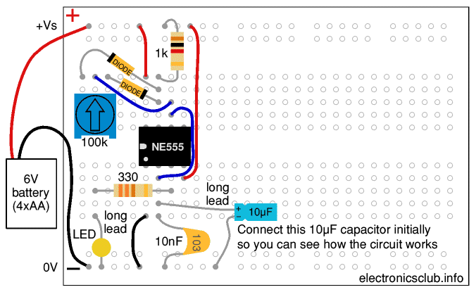
This project shows how two diodes and a variable resistor can be used with a 555 timer to make a PWM circuit for varying the brightness of an LED. It is a type of 555 astable circuit. The 10nF (= 0.01µF) capacitor can be connected either way round, your capacitor may be a different colour.
With both capacitors connected (as shown in the breadboard layout) the frequency is about 1Hz, this is too slow for controlling brightness but it allows you to see how the 'on time' of the LED changes as you turn the variable resistor. Notice how the frequency is almost constant because as the on time increases the off time decreases.
Now remove the 10µF capacitor, this increases the on/off frequency to about 1kHz (1000 times a second) which is too fast to see, instead we see an average brightness.
The diodes ensure that one part of the variable resistor track (plus 1kΩ) is used for the LED on time while the other part is used for the LED off time. This arrangement ensures that the total time per on/off cycle is almost constant while the on time is varied to control the LED brightness.
For more information see Duty Cycle.
When the 10nF and 10µF capacitors are connected in parallel their values add up. Their combined capacitance is effectively 10µF because 10nF (= 0.01µF) is 1000 times smaller and therefore insignificant relative to 10µF. Connecting a larger capacitor in parallel like this is a useful way to make an astable circuit temporarily run slowly so you can watch the circuit operate in 'slow motion'.
For more information see Capacitance.


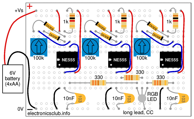
To produce a full range of colours from an RGB LED the brightness of each internal LED must be varied independently. This requires three 555 PWM circuits.
Remember to switch off (or disconnect) the battery before you add the two extra PWM circuits and the RGB LED.
Switch on, then adjust all three variable resistors to create a wide range of colours.
Red, green and blue are the primary colours of light. All colours can be made by mixing the right brightness of each these primary colours.
Read more: Colour vision


Three 555 PWM circuits are used for the RGB LED
Use parts from Workshops 1 to 3 plus:
Change the 330Ω resistors for the LEDs to 470Ω. You will also need a battery clip.
If you ordered parts from Rapid for Workshop 1 you will already have enough extras in the packs for most parts and will just need to order:
Most parts are supplied in packs but the extras are likely to be useful for other projects and it is good to have spares. Also see advice for building up a starter kit of parts.
Next page: Breadboard Workshops

There are more breadboard projects in these books from Amazon:
As an Amazon Associate, I earn from qualifying purchases. Any books you purchase through these links help to keep this website available for everyone to use free of charge.