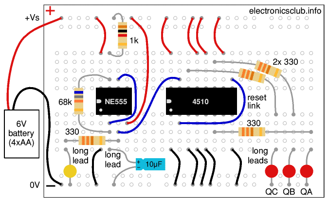
Breadboard Layout for Binary Counter:

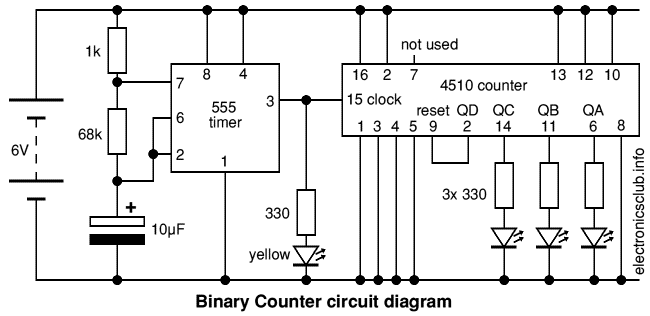
Circuit Diagram:


These projects introduce a binary counter and then use it to drive a RGB LED for 'counting with colours'.
Projects: Binary Counter | Counting with Colours | parts
Also see: Breadboard | 555 Astable | Counting Circuits | RGB LEDs
Next page: Breadboard Workshop 4
This project introduces a 4510 BCD (Binary Coded Decimal) counter. Binary Coded Decimal means the IC counts 0-9 in binary (0000 to 1001).
The counter's binary outputs are labelled QA (value 1), QB (value 2), QC (value 4) and QD (value 8) on the circuit diagram.
This project uses only the first 3 binary digits (also called 'bits') to count from 0 to 7 (000 to 111 in binary). This is known as a 3-bit binary counter.
Outputs QA, QB and QC connect to the red LEDs (via their resistors). An LED being lit represents '1' for its binary digit.
Output QD (pin 2) is connected by the blue wire labelled 'reset link' to the reset input (pin 9) so the counter immediately resets to zero when it reaches 8 (1000 in binary).
The 555 astable circuit on the left of the breadboard provides 1Hz clock pulses to drive the counter (pin 15 is the 4510 clock input). The yellow LED lights for each clock pulse and shows that this part of the circuit is working.
Unused inputs on CMOS ICs such as the 4510 should not be left unconnected because electrical noise may make them switch rapidly between states and upset the operation of the IC.
If necessary a 4516 4-bit binary counter can be used for this project, it needs the same connections as the 4510.
You might like to replace the 68kΩ resistor with a 100kΩ variable resistor. If you need help to do this see the Speed Control project of Breadboard Workshop 1.


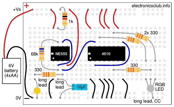
This project shows how the outputs of a 3-bit binary counter can be used to step through every on/off combination of the red, green and blue LEDs inside a RGB LED.
Remember to switch off (or disconnect) the battery before you change connections on the breadboard.
If you are continuing after building the previous Binary Counter project, this circuit is almost identical:
Switch on and watch the RGB LED count through 8 colours including white (red, green & blue all on) and black (all off).
Compare this project's binary counter with the 1-of-10 counter of the Traffic Light project using diodes to produce the sequence for the LEDs.
On circuit diagrams IC pins are arranged to help with understanding the circuit and usually not in the order found on the IC. For example, this project's circuit diagram shows the pins for outputs QD, QC, QB & QA in that order to match the order for the binary digits they represent (worth 8, 4, 2 & 1 respectively).


Use parts from Workshops 1 & 2 plus:
Change the 330Ω resistors for the LEDs to 470Ω. You will also need a battery clip.
Most parts are supplied in packs but the extras are likely to be useful for other projects and it is good to have spares. Also see advice for building up a starter kit of parts.
Next page: Breadboard Workshop 4