Uses | Connections | Building Circuit
Also see: Breadboard Workshops | Stripboard | PCB
A breadboard is used to make up temporary circuits for testing or to try out an idea. No soldering is required so it is easy to change connections and replace components. Parts are not damaged and can be re-used afterwards.
Almost all the Electronics Club website projects started life on a breadboard to check that the circuit worked as intended.
The photograph shows a typical small breadboard which is suitable for building simple circuits with one or two ICs (chips). Larger breadboards which are the size of two small breadboards are readily available too.
Rapid Electronics: small breadboard
Rapid Electronics: large breadboard

Small Breadboard
Photograph © Rapid Electronics
Breadboards have many tiny sockets (called 'holes') arranged on a 0.1" grid. The leads of most components can be pushed straight into the holes. ICs are inserted across the central gap with their notch or dot to the left.
Wire links can be made with single-core plastic-coated wire of 0.6mm diameter (the standard size), this is known as 1/0.6mm wire. I suggest buying a pack with several colours to help identify connections, red for +Vs wires, black for 0V, and so on.
Rapid Electronics: 1/0.6mm wire pack
Stranded wire is not suitable because it will crumple when pushed into a hole and it may damage the board if strands break off.
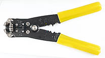
You will need wire strippers too.
Rapid Electronics: wire stripper

The two rows at the top and the two rows at the bottom are each linked horizontally all the way across as shown by the red and black lines on the diagram. The battery or power supply is connected to these rows, + (positive) at the top and 0V (zero volts, negative) at the bottom.
The other holes are linked in blocks of 5 as shown by blue lines. There are no links across the central section where ICs are placed. Notice how each pin of an IC is connected to 4 holes, the diagram shows this for three of the pins.
On the right hand side of the diagram you can see how a resistor and LED are connected so the LED will light when the battery or power supply is connected. You may like to leave this 'power on' indicator in place as a reminder while building your first few breadboard circuits because it is good to get into the habit of switching off or disconnecting the battery when making changes to a circuit.
You will need a battery to supply power to your breadboard circuits and I recommend a battery box which includes an on/off switch. All the breadboard circuits on this website need a 6V supply so a 4xAA cells battery box with switch is ideal. Use alkaline cells (best value) or zinc chloride cells (shorter life but cheaper). Do NOT use rechargeable cells because they can pass very high currents if there is a fault (a short circuit) and this may damage the breadboard or components, in extreme cases it may cause a fire.
Rapid Electronics: 4xAA battery box with switch | 4xAA alkaline cells
If you wish to use a 9V battery in most circuits the only components you will need to change are LED resistors: from 330Ω to 470Ω.
IC pins are numbered anti-clockwise around the IC starting near the notch or dot. The diagram shows the numbering for 8-pin and 16-pin ICs, but the principle is the same for all sizes.

Sometimes you will need to connect larger components such as switches and variable resistors to the breadboard and these may not have suitable leads of their own so you must solder some on yourself. Use single-core plastic-coated wire of 0.6mm diameter (the standard size). Stranded wire is not suitable because it will crumple when pushed into a hole and it may damage the board if strands break off.
On some larger breadboards there may be a break halfway along the top and bottom power supply rows. It is a good idea to check this and add a link across the gap if you find a break, otherwise part of your circuit will have no power!
Converting a circuit diagram to a breadboard layout is not straightforward because the arrangement of components on breadboard will look quite different from the circuit diagram.
When putting parts on breadboard you must concentrate on their connections, not their positions on the circuit diagram. The IC (chip) is a good starting point so place it across the centre of the breadboard and work round it pin by pin, putting in all the connections and components for each pin in turn.
The best way to explain this is by example, so the process of building this 555 astable circuit on breadboard is listed step-by-step below.
There's a parts list for this circuit at the bottom of the page.
555 astable circuit

Begin by carefully inserting the 555 IC across the central section of the breadboard with its notch or dot to the left.
Then deal with each pin of the 555:
Pin 1: connect a wire (black) to 0V (battery negative).
Pin 2: there are three connections here...
(i) connect a wire link to pin 6 (use any colour except red or black).
(ii) connect a 68kΩ resistor to pin 7, resistors can be connected either way round, find values using the resistor colour code.
(iii) connect a 10µF capacitor to 0V (battery negative), the long (+) lead connects to pin 2.
Pin 3: connect a 330Ω resistor to an unused block of 5 holes, then...
connect an LED (any colour) from that block to 0V (battery negative), note that the LED's long lead connects to the resistor.
Pin 4: connect a wire (red) to +Vs (battery positive).
Pin 5: there is no connection to pin 5 for this circuit.
Pin 6: there should be a wire already connected to pin 2.
Pin 7: connect a 1kΩ resistor to +Vs (battery positive).
There should be a 68kΩ resistor already connected to pin 2.
Pin 8: connect a wire (red) to +Vs (battery positive).
Finally...
If your circuit does not work disconnect (or switch off) the battery and carefully re-check every connection against the circuit diagram.
Leave this example circuit on the breadboard ready for the Breadboard Workshops.
You can see from the circuit diagram that R2 (the 68kΩ resistor) can be connected between pin 7 and either pin 2 or pin 6 because pins 2 and 6 are linked by a wire.
In a situation like this choose the pin which is most convenient for you. In this example pin 2 has been chosen because it gives a better spacing of the components and makes it easier to change R2 to another value.
Breadboards are perfect for experimenting because components can be easily changed and re-used. While changing components it is best to switch off or disconnect the battery to help avoid damage to the IC or other components, for example if component leads accidentally touch.
The on/off time period for this circuit is determined by R1, R2 and C1:
| T = 0.7 × (R1 + 2R2) × C1 |
Note that R1 must be 1kΩ or more. If R2 is much greater than R1 the LED on and off times are almost equal.
For further information see the 555 astable page.
Build a similar project by soldering on stripboard: Flashing LED on stripboard
Change the 330Ω resistor for the LED to 470Ω. You will also need a battery clip.
Most parts are supplied in packs but the extras are likely to be useful for other projects. Also see advice for building up a starter kit of parts.
There are projects to build in the Breadboard Workshops with clear diagrams showing the breadboard layout. No soldering is required and the parts can be used again in other projects. Circuit diagrams are provided to help you understand the operation of each circuit.
Next: Breadboard Workshops