
Colour code | Tolerance | E6/E12 series | Power rating
Also see: Resistance | Ohm's Law | Variable Resistors
Resistors restrict the flow of electric current, for example a resistor is placed in series with a light-emitting diode (LED) to limit the current passing through the LED.
Resistors may be connected either way round and they are not damaged by heat when soldering.
Resistance is measured in ohms, symbol Ω (omega). 1Ω is quite small so resistor values are also given in kΩ and MΩ:
1kΩ = 1000Ω
1MΩ = 1000kΩ
= 1000 000Ω.
Most resistors are too small to show their resistance as a printed number. A colour code is used instead.
For information on resistors connected in series and parallel please see the resistance page.
Rapid Electronics: Resistors
Resistor values are often written on circuit diagrams using a code system which avoids using a decimal point because it is easy to miss the small dot. Instead the letters R, K and M are used in place of the decimal point.
To read the code: replace the letter with a decimal point, then multiply the value by 1000 if the letter was K, or 1000 000 if the letter was M. The letter R means multiply by 1.
For example:
Resistor values are usually shown using coloured bands, each colour represents a number as shown in the table. Most resistors have 4 bands:
This resistor has red (2), violet (7), yellow (4 zeros) and gold bands so its value is 270000Ω = 270kΩ (usually shown as 270K on circuit diagrams).
Make your own Colour Code Calculator.
| Electronics Colour Code | |
| Colour | Number |
| Black | 0 |
| Brown | 1 |
| Red | 2 |
| Orange | 3 |
| Yellow | 4 |
| Green | 5 |
| Blue | 6 |
| Violet | 7 |
| Grey | 8 |
| White | 9 |
The standard colour code cannot show values of less than 10Ω. To show smaller values two special colours are used for the third band:
The first and second bands represent the digits in the usual way.
For example:
red, violet, gold bands represent 27 × 0.1 = 2.7Ω.
green, blue, silver bands represent 56 × 0.01 = 0.56Ω.
This calculator can be used to identify resistor values. It consists of three card discs showing the colours and values, these are fastened together so you can simply turn the discs to select the value or colour code required. Simple but effective!
There are two versions to download and print on A4 white card (two calculators per sheet):
To make the calculator: cut out the three discs and fasten them together with a brass paper fastener. The Black & White version must be coloured by you using pencils or pens and it is easiest to do this before cutting out.
The tolerance of a resistor is shown by the fourth band of the colour code. Tolerance is the precision of the resistor and it is given as a percentage.
For example a 390Ω resistor with a tolerance of ±10% will have a value within 10% of 390Ω, between 390 - 39 = 351Ω and 390 + 39 = 429Ω (39 is 10% of 390).
A special colour code is used for the fourth band tolerance:
Tolerance may be ignored for almost all circuits because a precise resistor value is rarely required and where it is a variable resistor will usually be used.


You may have noticed that resistors are not available with every possible value, for example 22kΩ and 47kΩ are readily available, but 25kΩ and 50kΩ are not!
Why is this? Imagine that you decided to make resistors every 10Ω giving 10, 20, 30, 40, 50 and so on. That seems fine, but what happens when you reach 1000? It would be pointless to make 1000, 1010, 1020, 1030 and so on because for these values 10 is a very small difference, too small to be noticeable in most circuits.
To produce a sensible range of resistor values you need to increase the size of the 'step' as the value increases. The standard resistor values are based on this idea and they form a series which follows the same pattern for every multiple of ten.
A similar arrangement is used for money: the step size of coins and notes increases as the value increases.
For example UK currency (£1 = 100p) has 1p, 2p, 5p, 10p, 20p, 50p, £1 & £2 coins
(plus £5, £10, £20 & £50 notes).
The E6 series has 6 values for each multiple of ten, it is used for resistors with 20% tolerance. The values are: 10, 15, 22, 33, 47, 68, ... then it continues 100, 150, 220, 330, 470, 680, 1000 etc. Notice how the step size increases as the value increases. For this series the step (to the next value) is roughly half the value.
The E12 series has 12 values for each multiple of ten, it is used for resistors with 10% tolerance. The values are 10, 12, 15, 18, 22, 27, 33, 39, 47, 56, 68, 82, ... then it continues 100, 120, 150 etc. Notice how this is the E6 series with an extra value in each gap.
It allows you to choose a value within 10% of the precise value you need. This is sufficiently accurate for almost all projects and it is sensible because most resistors have a tolerance of ±10%.
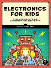
A great introduction, this book starts by assuming no previous knowledge then carefully builds up straightforward explanations of how components work, plus practical techniques including wire-stripping, soldering and using a multimeter. The final project uses three ICs to make a great game.
The author, Øyvind Nydal Dahl, has done a great job in providing clear step-by-step instructions with breadboard (or stripboard) layouts as well as circuit diagrams for projects. As Technical Reviewer for the book I've built all the projects myself and I'm very happy to recommend it to anyone looking for a fun and educational introduction to electronics.
Electrical energy is converted to heat when current flows through a resistor. Usually the effect is negligible, but if the resistance is low, or the voltage across the resistor is high, a large current may pass making the resistor become noticeably warm. The resistor must be able to withstand the heating effect and resistors have power ratings to show this.
Power ratings of resistors are rarely quoted in parts lists because for most circuits the standard power ratings of 0.25W or 0.5W are suitable. For the rare cases where a higher power is required it should be clearly specified in the parts list, these will be circuits using low value resistors (less than about 300Ω) or high voltages (more than 15V).
Rapid Electronics: Power Resistors
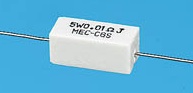
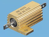
High power resistors
(5W top, 25W bottom)
Photographs © Rapid Electronics
The power, P, developed in a resistor can be worked out using these equations:
| P = V² / R or P = I² × R |
P = power developed in watts (W)
I = current through resistor in amps (A)
R = resistance of resistor in ohms (Ω)
V = voltage across resistor in volts (V)
Rapid Electronics have kindly allowed me to use their images on this website and I am very grateful for their support. They stock a wide range of resistors and other components for electronics and I am happy to recommend them as a supplier.
As an Amazon Associate, I earn from qualifying purchases. Any book you purchase through the Amazon links helps to keep this website available for everyone to use free of charge.
Next page: Switches