
How to solder | Heat sink | Components | Solder | Desoldering | Burns
For information about soldering irons and other tools please see the Tools page.
Download a PDF version of this page: Soldering Guide (PDF)
Never touch the element or tip of the soldering iron. They are very hot (about 400°C) and will give you a nasty burn.
Take great care to avoid touching the mains flex with the tip of the iron. The iron should have a heatproof flex for extra protection. An ordinary plastic flex will melt immediately if touched by a hot iron and there is a serious risk of burns and electric shock.
Always return the soldering iron to its stand when not in use. Never put it down on your workbench, even for a moment!
Work in a well-ventilated area. The smoke formed as you melt solder is mostly from the flux and quite irritating. Avoid breathing it by keeping you head to the side of, not above, your work.
Wash your hands after using solder. Traditional solder contains lead which is a poisonous metal.
If you burn yourself see First Aid for Burns.

I strongly recommend using a soldering iron with a heatproof silicone cable for safety because it will not melt if accidentally touched with the hot iron.
For example this 230V soldering iron from Rapid Electronics: soldering iron
Place the soldering iron in its stand and plug in. The iron will take a few minutes to reach its operating temperature of about 400°C.
Dampen the sponge in the stand. The best way to do this is to lift it out the stand and hold it under a cold tap for a moment, then squeeze to remove excess water. It should be damp, not dripping wet.
Wait a few minutes for the soldering iron to warm up. You can check if it is ready by trying to melt a little solder on the tip.
Wipe the tip of the iron on the damp sponge. This will clean the tip.
Melt a little solder on the tip of the iron. This is called 'tinning' and it will help the heat to flow from the iron's tip to the joint. It only needs to be done when you plug in the iron, and occasionally while soldering if you need to wipe the tip clean on the sponge.
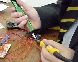
Hold the soldering iron like a pen, near the base of the handle (imagine you are going to write your name). Remember to never touch the hot element or tip.
Touch the soldering iron onto the joint to be made. Make sure it touches both the component lead and the track. Hold the tip there for a few seconds and...
Feed a little solder onto the joint. It should flow smoothly onto the lead and track to form a volcano shape as shown in the diagram. Apply the solder to the joint, not the iron.
Remove the solder, then the iron, while keeping the joint still. Allow the joint a few seconds to cool before you move the circuit board.
Inspect the joint closely. It should look shiny and have a 'volcano' shape. If not, you will need to reheat it and feed in a little more solder. This time ensure that both the lead and track are heated fully before applying solder.
If you burn yourself see First Aid for Burns below.

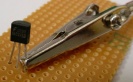
Some components, such as transistors, can be damaged by heat when soldering so if you are not an expert it is wise to use a heat sink clipped to the lead between the joint and the component body. You can buy a special tool, but a standard crocodile clip (without a plastic cover) works just as well and is cheaper.
The heat sink works by taking some of the heat being supplied by the soldering iron and this helps to prevent the component's temperature increasing too much.
Rapid Electronics: crocodile clip

It is very tempting to start soldering components onto the circuit board straight away, but please take time to identify all the parts first. Sticking them onto a sheet of scrap paper and labelling each one is worthwhile and you are less likely to make a mistake if you do this.
Some ICs are static sensitive and will be supplied in antistatic packaging - leave these ICs in their packaging until you need them, then earth your hands by touching a metal water pipe or window frame before handling the ICs.
Many must be placed the correct way round and a few can be easily damaged by the heat from soldering.
The table shows advice for the various components and a suggested order to put them on the board. Generally it is best to start with the smallest parts but for stripboard it is helpful to start with the IC holder(s) as a reference point for other parts.
Wire links between points on the board can be made with plastic-coated single core wire which will need stripping, or tinned copper wire if the link won't touch other parts. Tinned copper wire looks just like solder but you can feel the difference, it is stiffer than solder (and it won't melt).
Wires to parts off the board need to be flexible so use plastic-coated stranded wire for these, a popular type is 7/0.2mm wire (7 strands of 0.2 mm diameter wire). Single core wire is unsuitable because it snaps when repeatedly flexed.
Rapid Electronics: 7/0.2mm wire pack
| Soldering Components Put components on the board in this order: |
 1. IC Holders
Connect the correct way round - the notch will remind you which way to place the IC. Do NOT insert the ICs yet. |
Connect either way round. |
3. Small value capacitors

Small value capacitors (< 1µF) are not polarised. Connect either way round. |
4. Electrolytic capacitors (1µF +)

Connect the correct way round, look for a + or - near one lead. They may be radial style (both leads at one end) or axial style (leads at each end). |
Connect the correct way round. The stripe marks the cathode (line on symbol) usually labelled k on diagrams. For germanium diodes use a heat sink. |
 6. LEDs
Connect the correct way round, the cathode is the short lead. The diagram will have a or + for anode, k or - for cathode. |
 7. Transistors
Transistors have 3 'legs' (leads) so take extra care to connect them correctly. They can be damaged by heat, use a heat sink until you can solder quickly. |
Links between points on the board can be made with plastic-coated single core wire, or tinned copper wire if the link won't touch other parts. |
| 9. Parts with their own wires
Battery clips, buzzers etc. Connect the correct way round if necessary. |
| 10. Wires to parts off the board
Use stranded wire for switches, relays, loudspeakers, variable resistors etc. |
11. ICs (chips)

Connect the correct way round, look for the notch or dot near pin 1. Make sure all the pins are lined up with the socket before pushing down firmly with your thumb. |


Traditional solder is an alloy (mixture) of tin and lead, typically 60% tin and 40% lead. It melts at a temperature of about 200°C.
Modern lead-free solder is an alloy of tin with other metals including copper and silver. It melts at a temperature of about 220°C.
Coating a surface with solder is called 'tinning' because of the tin content of solder.
Photograph © Rapid Electronics
Always wash your hands after using solder, this is especially important with traditional solder because it contains lead which is toxic.
The best size of solder for electronics is 22 swg (swg = standard wire gauge) and I recommend using lead-free solder.
Rapid Electronics: lead-free solder
Solder for electronics use contains tiny cores of flux, like the wires inside a mains flex. The flux is corrosive, like an acid, and it cleans the metal surfaces as the solder melts. This is why you must melt the solder actually on the joint, not on the iron tip. Without flux most joints would fail because metals quickly oxidise and the solder itself will not flow properly onto a dirty, oxidised, metal surface.
At some stage you will probably need to desolder a joint to remove or re-position a wire or component. There are two ways to remove the solder:
Also known as a 'solder sucker'. It is best to use one with an ESD (electrostatic discharge) nozzle to protect some ICs which can be damaged by static electricity.
Rapid Electronics: desolder pump
Using a desoldering pump (solder sucker)
The copper braid acts as a wick for the molten solder which readily flows onto the braid, away from the joint.
Rapid Electronics: desolder braid

Solder remover braid
Photograph © Rapid Electronics
After removing most of the solder from the joint(s) you may be able to remove the wire or component lead straight away (allow a few seconds for it to cool). If the joint will not come apart easily apply your soldering iron to melt the remaining traces of solder at the same time as pulling the joint apart, taking care to avoid burning yourself.
Most burns from soldering are likely to be minor and treatment is simple:
To reduce the risk of burns:
Rapid Electronics have kindly allowed me to use their images on this website and I am very grateful for their support. They stock a wide range of components, tools and materials for electronics and I am happy to recommend them as a supplier.
