
Next Page: Meters
Also See: Multimeters | Ohm's Law
Voltage and Current are vital to understanding electronics, but they are quite hard to grasp because we cannot see them directly.
Voltage attempts to make a current flow, and current will flow if the circuit is complete. Voltage is sometimes described as the 'push' or 'force' of the electricity, it isn't really a force but this may help you to imagine what is happening. It is possible to have voltage without current, but current cannot flow without voltage.
Voltage and Current
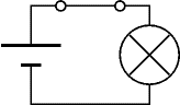
The switch is closed making
a complete circuit so
current can flow.
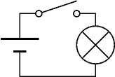
Voltage but No Current
The switch is open so
the circuit is broken and
current cannot flow.
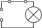
No Voltage and No Current
Without the cell there is
no source of voltage so
current cannot flow.
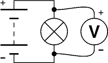
Connecting a voltmeter in parallel
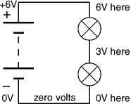
Voltage is a difference between two points, but in electronics we often refer to voltage at a point meaning the voltage difference between that point and a reference point of 0V (zero volts).
Zero volts could be any point in the circuit, but to be consistent it is normally the negative terminal of the battery or power supply. You will often see circuit diagrams labelled with 0V as a reminder.
You may find it helpful to think of voltage like height in geography. The reference point of zero height is the mean (average) sea level and all heights are measured from that point. The zero volts in an electronic circuit is like the mean sea level in geography.
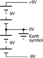
Some circuits require a dual supply with three supply connections as shown in the diagram. For these circuits the zero volts reference point is the middle terminal between the two parts of the supply.
On complex circuit diagrams using a dual supply the earth symbol is often used to indicate a connection to 0V, this helps to reduce the number of wires drawn on the diagram.
The diagram shows a ±9V dual supply, the middle terminal is 0V.
1A (1 amp) is quite a large current for electronics, so mA (milliamp) is often used. m (milli) means 'thousandth':
1mA = 0.001A, or 1000mA = 1A
The need to break the circuit to connect in series means that ammeters are difficult to use on soldered circuits. Most testing in electronics is done with voltmeters which can be easily connected without disturbing circuits.
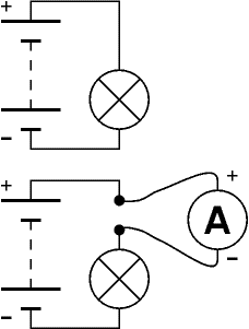
Connecting an ammeter in series


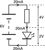
In this circuit the 4V across the resistor and the 2V across the LED add up to the battery voltage: 2V + 4V = 6V.
The current through all parts (battery, resistor and LED) is 20mA.
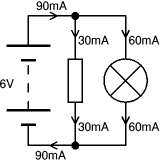
In this circuit the battery, resistor and lamp all have 6V across them.
The 30mA current through the resistor and the 60mA current through the lamp add up to the 90mA current through the battery.

A great introduction, this book starts by assuming no previous knowledge then carefully builds up straightforward explanations of how components work, plus practical techniques including wire-stripping, soldering and using a multimeter. The final project uses three ICs to make a great game.
The author, Øyvind Nydal Dahl, has done a great job in providing clear step-by-step instructions with breadboard (or stripboard) layouts as well as circuit diagrams for projects. As Technical Reviewer for the book I've built all the projects myself and I'm very happy to recommend it to anyone looking for a fun and educational introduction to electronics.
As an Amazon Associate, I earn from qualifying purchases. Any book you purchase through the Amazon link helps to keep this website available for everyone to use free of charge.