Types | Connecting | Soldering | Testing | Codes | Choosing | Heat sinks
This page covers practical matters such as precautions when soldering and identifying leads. For information on the operation and use of transistors in circuits please see the transistor circuits page.
Transistors amplify current, for example they can be used to amplify the small output current from a logic IC so that it can operate a lamp, relay or other high current device. In many circuits a resistor is used to convert the changing current to a changing voltage, so the transistor is being used to amplify voltage.
A transistor may be used as a switch (either fully on with maximum current, or fully off with no current) and as an amplifier (always partly on).
The amount of current amplification is called the current gain, symbol hFE (one of many parameters for transistors, each with their own symbol).

Rapid Electronics: transistors

There are two types of standard (bipolar junction) transistors, NPN and PNP, with different circuit symbols as shown. The letters refer to the layers of semiconductor material used to make the transistor. Most transistors used today are NPN because this is the easiest type to make from silicon. If you are new to electronics it is best to start by learning how to use NPN transistors.
The leads are labelled base (B), collector (C) and emitter (E). These terms refer to the internal operation of a transistor but they are not much help in understanding how a transistor is used, so just treat them as labels.
A Darlington pair is two transistors connected together to give a very high current gain.
In addition to bipolar junction transistors, there are field-effect transistors which are usually referred to as FETs. They have different circuit symbols and properties and they are not covered by this page.
Transistors have three leads which must be connected the correct way round. Take care because a wrongly connected transistor may be damaged instantly when you switch on.
The orientation of the transistor may be clear from the PCB or stripboard layout diagram, otherwise you will need to refer to a supplier's catalogue or website to identify the leads.
The drawings show the leads for some common transistor case styles.
Note that transistor lead diagrams show the view from below with the leads towards you. This is the opposite of IC pin diagrams which show the view from above.
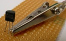
Transistors can be damaged by heat when soldering so if you are not an expert it is wise to use a heat sink clipped to the lead between the joint and the transistor body. You can buy a special tool, but a standard crocodile clip (without a plastic cover) works just as well and is cheaper.
Do not confuse this temporary heat sink with the permanent heat sink (described below) which may be required for a power transistor to prevent it overheating during operation.
Transistors can be damaged by heat when soldering or by misuse in a circuit. If you suspect that a transistor may be damaged there are two easy ways to test it:
Use a multimeter or a simple tester (battery, resistor and LED) to check each pair of leads for conduction. Set a digital multimeter to diode test and an analogue multimeter to a low resistance range.
Test each pair of leads both ways (six tests in total):
The diagram shows how the junctions behave in an NPN transistor. The diodes are reversed in a PNP transistor but the same test procedure can be used.
Testing an NPN transistor
Connect the transistor into the simple circuit shown. The supply voltage is not critical, anything between 5V and 12V is suitable. This circuit can be quickly built on breadboard for example. Take care to include the 10kΩ resistor in the base connection or you will destroy the transistor as you test it!
If the transistor is OK the LED should light when the switch is pressed and not light when the switch is released.
To test a PNP transistor use the same circuit but reverse the LED and the supply voltage.
Some multimeters have a 'transistor test' function which provides a known base current and measures the collector current so as to display the transistor's DC current gain hFE.

A simple switching circuit
to test an NPN transistor


There are three main series of transistor codes used in the UK:
The first letter B is for silicon, A is for germanium (rarely used now). The second letter indicates the type; for example C means low power audio frequency; D means high power audio frequency; F means low power high frequency. The rest of the code identifies the particular transistor. There is no obvious logic to the numbering system. Sometimes a letter is added to the end (eg BC108C) to identify a special version of the main type, for example a higher current gain or a different case style. If a project specifies a higher gain version (BC108C) it must be used, but if the general code is given (BC108) any transistor with that code is suitable.
TIP refers to the manufacturer: Texas Instruments Power transistor. The letter at the end identifies versions with different voltage ratings.
The initial '2N' identifies the part as a transistor and the rest of the code identifies the particular transistor. There is no obvious logic to the numbering system.
Most projects will specify a particular transistor but you can usually substitute an equivalent transistor from the wide range available. The most important properties to look for are the maximum collector current IC and the current gain hFE. To make selection easier most suppliers group their transistors in categories determined either by their typical use or maximum power rating.
To make a final choice you may need to consult tables of technical data provided in catalogues, books and on-line. They contain a great deal of useful information but can be difficult to understand if you are not familiar with the terms and abbreviations used.
These are some of the terms you are likely to see:
Structure - type of transistor, NPN or PNP, a substitute must be the same type.
Case style - layout of the leads.
IC max. - maximum collector current.
VCE max. - maximum voltage across the collector-emitter junction, ignore this for low voltage circuits.
hFE - the current gain (strictly the DC current gain). The guaranteed minimum value is given because the actual value varies from transistor to transistor - even for those of the same type! Note that current gain is just a number so it has no units. The gain is often quoted at a particular collector current IC which is usually in the middle of the transistor's range, for example '100@20mA' means the gain is at least 100 at 20mA. Sometimes minimum and maximum values are given. Since the gain is roughly constant for various currents but it varies from transistor to transistor this detail is only really of interest to experts.
Ptot max. - maximum total power which can be developed in the transistor, note that a heat sink will be required to achieve the maximum rating. This rating is important for transistors operating as amplifiers, the power is roughly IC × VCE. For transistors operating as switches the maximum collector current (IC max.) is more important.
Category - typical use for the transistor, a good starting point when looking for a substitute. There may be separate tables for different categories.
Possible substitutes - transistors with similar electrical properties which will be suitable substitutes in most circuits. They may have a different case style so take care when placing on the circuit board.
Rapid Electronics: transistors
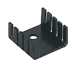
Heat sinks are needed for transistors passing large currents.
Waste heat is produced in transistors due to the current flowing through them. If you find that a transistor is becoming too hot to touch it certainly needs a heat sink! The heat sink helps to dissipate (remove) the heat by transferring it to the surrounding air.
Photograph © Rapid Electronics
The rate of producing waste heat is called the thermal power, P. Usually the base current IB is too small to contribute much heat, so the thermal power is determined by the collector current IC and the voltage VCE across the transistor:
| P = IC × VCE |
The heat is not a problem if IC is small or if the transistor is used as a switch because when 'full on' VCE is almost zero. However, power transistors used in circuits such as an audio amplifier or a motor speed controller will be partly on most of the time and VCE may be about half the supply voltage. These power transistors will almost certainly need a heat sink to prevent them overheating.
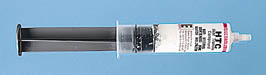
Power transistors usually have bolt holes for attaching heat sinks, but clip-on heat sinks are also available. Make sure you use the right type for your transistor. Many transistors have metal cases which are connected to one of their leads so it may be necessary to insulate the heat sink from the transistor. Insulating kits are available with a mica sheet and a plastic sleeve for the bolt. Heat-conducting paste can be used to improve heat flow from the transistor to the heat sink, this is especially important if an insulation kit is used.
Heat sinks are rated by their thermal resistance (Rth) in °C/W. For example 2°C/W means the heat sink (and therefore the component attached to it) will be 2°C hotter than the surrounding air for every 1W of heat it is dissipating. Note that a lower thermal resistance means a better heat sink.
| P = IC × VCE |
| Rth = (Tmax - Tair) / P |
If the steps above seem too complex you can try attaching a moderately large heat sink and hope for the best. Cautiously monitor the transistor temperature with your finger, if it becomes painfully hot switch off immediately and use a larger heat sink.
Rapid Electronics: heat sinks
The term 'thermal resistance' is used because it is analagous to electrical resistance:
Rapid Electronics have kindly allowed me to use their images on this website and I am very grateful for their support. They stock a wide range of transistors and other components for electronics and I am happy to recommend them as a supplier.
As an Amazon Associate, I earn from qualifying purchases. Any book you purchase through the Amazon links helps to keep this website available for everyone to use free of charge.
Next page: Variable Resistors