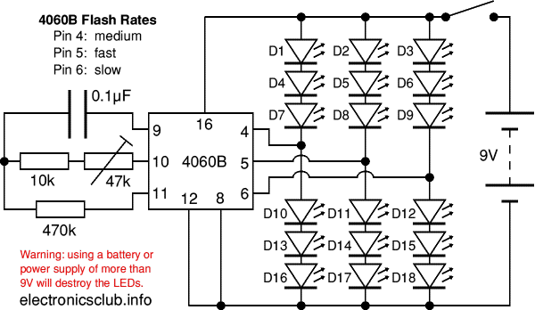
This project flashes 18 LEDs at three different rates and you can use these to create an eye-catching Christmas Decoration. The circuit is kept simple (and low cost) by using the 4060B IC which is a counter and oscillator (clock) in one package. This project must have a 9V supply, such as a PP3 battery. It will not work with lower voltages and a higher voltage will destroy the LEDs.
The preset variable resistor can be used to adjust the oscillator frequency and this determines the flash rate of the LEDs. The IC limits the current to and from its outputs so the LEDs can be safely connected without resistors in series to limit the current. The stripboard part of the circuit is easy to build but the wiring for the LEDs needs care so detailed instructions are provided below.
You can download a Christmas Tree template to print out and glue onto thick card, hardboard etc.

Warning! This project must have a 9V supply.
Using a battery (or power supply) with a voltage greater than 9V will destroy the LEDs.


