LDR | Thermistor | Piezo | Loudspeaker | Buzzer/Bleeper | Inductor (coil)

An LDR is an input transducer (sensor) which converts brightness (light) to resistance. Its resistance decreases as the brightness of light increases.
A multimeter can be used to find the resistance in darkness and bright light, these are the typical results for a standard LDR:
For many years the standard LDR was the ORP12 or NORPS12, about 13mm diameter. Smaller LDRs are also available and their diameter is about 5mm.
An LDR may be connected either way round and no special precautions are required when soldering.
Amazon: LDR (not available from Rapid Electronics)
Photograph © Rapid Electronics

A thermistor is an input transducer (sensor) which converts temperature (heat) to resistance.
Almost all thermistors have a negative temperature coefficient (NTC) which means their resistance decreases as their temperature increases. It is possible to make thermistors with a positive temperature coefficient (PTC, resistance increases as temperature increases) but these are rarely used. Always assume NTC if no information is given.
A multimeter can be used to find the resistance at various temperatures, these are some typical readings for example:
Suppliers usually specify thermistors by their resistance at 25°C (room temperature). Thermistors take several seconds to respond to a sudden temperature change, small thermistors respond more rapidly.
A thermistor may be connected either way round and no special precautions are required when soldering. If it is going to be immersed in water the thermistor and its connections should be insulated because water is a weak conductor; for example they could be coated with polyurethane varnish.
Rapid Electronics: thermistors
Photograph © Rapid Electronics


Piezo transducers are output transducers which convert an electrical signal to sound. They require a driver circuit (such as a 555 astable) to provide a signal and if this is near their natural (resonant) frequency of about 3kHz they will produce a particularly loud sound.
Piezo transducers require a small current, usually less than 10mA, so they can be connected directly to the outputs of most ICs. They are ideal for buzzes and bleeps, but are not suitable for speech or music because they distort the sound. They are sometimes supplied with red and black leads, but they may be connected either way round. PCB-mounting versions are also available.
Piezo transducers can also be used as input transducers for detecting sudden loud noises or impacts, effectively behaving as a crude microphone.
Rapid Electronics: piezo transducer
Photograph © Rapid Electronics


Loudspeakers are output transducers which convert an electrical signal to sound. Usually they are called 'speakers'. They require a driver circuit, such as a 555 astable or an audio amplifier, to provide a signal. There is a wide range available, but for many electronics projects a 300mW miniature loudspeaker is ideal.
This type is about 70mm diameter and it is usually available with resistances of 8Ω and 64Ω. If a project specifies a 64Ω speaker you must use this higher resistance to prevent damage to the driving circuit.
Loudspeakers may be connected either way round except in stereo circuits when the + and - markings on their terminals must be observed to ensure the two speakers are in phase.
Correct polarity must always be observed for large speakers in cabinets because the cabinet may contain a small circuit (a 'crossover network') which diverts the high frequency signals to a small speaker (a 'tweeter') because the large main speaker is poor at reproducing them.
Miniature loudspeakers can also be used as a microphone and they work surprisingly well, certainly good enough for speech in an intercom system for example.
Rapid Electronics: loudspeakers
Photograph © Rapid Electronics
Most circuits used to drive loudspeakers produce an audio (AC) signal which is combined with a constant DC signal. The DC will make a large current flow through the speaker due to its low resistance, possibly damaging both the speaker and the driving circuit. To prevent this happening a large value electrolytic capacitor is connected in series with the speaker as shown in the diagram, this blocks DC but passes audio (AC) signals. See capacitor coupling.

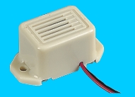
These devices are output transducers converting electrical energy to sound. They contain an internal oscillator to produce the sound which is set at about 400Hz for buzzers and about 3kHz for bleepers.
Buzzers have a voltage rating but it is only approximate, for example 6V and 12V buzzers can be used with a 9V supply. Their typical current is about 25mA.
Bleepers have wide voltage ranges (such as 3-30V) and they pass a low current of about 10mA.
Suppliers may describe bleepers as 'piezo buzzers' or 'piezo transducers'. Unfortunately the second term can lead to confusion because as well as a piezo transducer it also has a built-in circuit to produce the bleep tone. Read the supplier's information carefully to ensure you have the right type.
An inductor is a coil of wire which may have a core of air, iron or ferrite (a brittle material made from iron). Its electrical property is called inductance and the unit for this is the henry, symbol H. 1H is very large so mH and µH are used, 1000µH = 1mH and 1000mH = 1H. Iron and ferrite cores increase the inductance.
Inductors are mainly used in tuned circuits and to block high frequency AC signals (they are sometimes called chokes). They pass DC easily, but block AC signals, this is the opposite of capacitors.
Inductors are rarely found in simple projects, one exception is the tuning coil of a radio receiver. You may have to make the coil yourself by neatly winding enamelled copper wire around a ferrite rod. Enamelled copper wire has very thin insulation (allowing the turns of the coil to be close together) so it cannot be stripped in the usual way - a good method is to gently pull the ends of the wire through folded emery paper.
An inductor may be connected either way round and no special precautions are required when soldering.
Rapid Electronics: inductors | ferrite rod
![]()
Circuit symbol
![]()
Inductor (miniature)

Ferrite rod
Photographs © Rapid Electronics
Ferrite rods are brittle so treat them like glass, not iron!
Rapid Electronics have kindly allowed me to use their images on this website and I am very grateful for their support. They stock a wide range of components for electronics and I am happy to recommend them as a supplier.
As an Amazon Associate, I earn from qualifying purchases. Any book you purchase through the Amazon links helps to keep this website available for everyone to use free of charge.
Next page: Starter Kit of Components