Impedance can be split into two parts:
- Resistance R (the part which is constant regardless of frequency)
- Reactance X (the part which varies with frequency due to capacitance and inductance)


Impedance | Reactance | Input Impedance | Output Impedance | Voltage Divider Impedance
Next Page: Analogue & Digital
Also See: Capacitance | Resistance
Impedance (symbol Z) is a measure of the overall opposition of a circuit to current, in other words: how much the circuit impedes the flow of charge. It is like resistance, but it also takes into account the effects of capacitance and inductance. Impedance is measured in ohms (Ω).
Impedance is more complex than resistance because the effects of capacitance and inductance vary with the frequency of the current passing through the circuit and this means impedance varies with frequency. The effect of resistance is constant regardless of frequency.
| Impedance, Z = | V |
| I |
| Resistance, R = | V |
| I |
V = voltage in volts (V)
I = current in amps (A)
Z = impedance in ohms (Ω)
R = resistance in ohms (Ω)
The term 'impedance' is often used (quite correctly) for simple circuits which have no capacitance or inductance, for example to refer to their 'input impedance' or 'output impedance'. This may seem confusing at first but for these simple circuits you can assume it is just another word for resistance.

The capacitance and inductance cause a phase shift (see note) between the current and voltage which means that the resistance and reactance cannot be simply added up to give impedance. Instead they must be added as vectors with reactance at right angles to resistance as shown in the diagram.
Four electrical quantities determine the impedance (Z) of a circuit: resistance (R), capacitance (C), inductance (L) and frequency (f).
The following section on reactance explains how capacitance, inductance and frequency affect impedance.
Phase shift means that the current and voltage are out of step with each other. Think of charging a capacitor. When the voltage across the capacitor is zero, the current is at a maximum; when the capacitor has charged and the voltage is at a maximum, the current is at a minimum. The charging and discharging occur continually with AC and the current reaches its maximum shortly before the voltage reaches its maximum: so we say the current leads the voltage.
Reactance (symbol X) is a measure of the opposition of capacitance and inductance to current. Reactance varies with the frequency of the electrical signal. Reactance is measured in ohms (Ω).
There are two types of reactance: capacitive reactance (Xc) and inductive reactance (XL).
The total reactance (X) is the difference between the two:
| Total Reactance, X = XL - Xc |
Capacitive reactance (Xc) is large at low frequencies and small at high frequencies. For steady DC which is zero frequency (f = 0Hz), Xc is infinite (total opposition), which means that capacitors pass AC but block DC.
| Capacitive Reactance, Xc = | 1 |
| 2πfC |
Xc = reactance in ohms (Ω)
f = frequency in hertz (Hz)
C = capacitance in farads (F)
For example: a 1µF capacitor has a reactance of 3.2kΩ for a 50Hz signal, but when the frequency is higher at 10kHz its reactance is only 16Ω.
Inductive reactance, XL is small at low frequencies and large at high frequencies. For steady DC (frequency zero), XL is zero (no opposition), which means that inductors pass DC but block high frequency AC.
| Inductive Reactance, XL = 2πfL |
XL = reactance in ohms (Ω)
f = frequency in hertz (Hz)
L = inductance in henrys (H)
For example: a 1mH inductor has a reactance of only 0.3Ω for a 50Hz signal, but when the frequency is higher at 10kHz its reactance is 63Ω.
Input impedance (ZIN) is the impedance 'seen' by anything connected to the input of a circuit or device (such as an amplifer). It is the combined effect of all the resistance, capacitance and inductance connected to the input inside the circuit or device.
It is normal to use the term 'input impedance' even for simple cases where there is only resistance and the term 'input resistance' could be used instead. In fact it is usually reasonable to assume that an input impedance is just resistance providing the input signal has a low frequency (less than 1kHz).

The effects of capacitance and inductance vary with frequency, so if these are present the input impedance will vary with frequency. The effects of capacitance and inductance are generally most significant at high frequencies.
Usually input impedances should be high, at least ten times the output impedance of the circuit (or component) supplying a signal to the input. This ensures that the input will not 'overload' the source of the signal and reduce the strength (voltage) of the signal by a substantial amount.
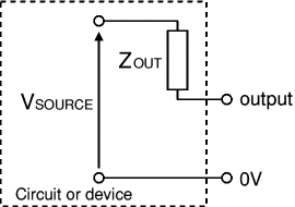
The output of any circuit or device is equivalent to an output impedance (ZOUT) in series with a perfect voltage source (VSOURCE). This is called the equivalent circuit and it represents the combined effect of all the voltage sources, resistance, capacitance and inductance connected to the output inside the circuit or device. Note that VSOURCE is usually not the same as the supply voltage Vs.
It is normal to use the term 'output impedance' even for simple cases where there is only resistance and the term 'output resistance' could be used instead. In fact it is usually reasonable to assume that an output impedance is just resistance providing the output signal has a low frequency (less than 1kHz).

The equivalent circuit of any output
The effects of capacitance and inductance vary with frequency, so if these are present the output impedance will vary with frequency. The effects of capacitance and inductance are generally most significant at high frequencies.
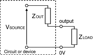
Usually output impedances should be low, less than a tenth of the load impedance connected to the output. If an output impedance is too high it will be unable to supply a sufficiently strong signal to the load because most of the signal's voltage will be 'lost' inside the circuit driving current through the output impedance ZOUT. The load could be a single component or the input impedance of another circuit.
Low output impedance, ZOUT << ZLOAD
Most of VSOURCE appears across the load, very little voltage is 'lost'
driving the output current through the output impedance. Usually this is the best arrangement.
Matched impedances, ZOUT = ZLOAD
Half of VSOURCE appears across the load, the other half is 'lost'
driving the output current through the output impedance. This arrangement is useful in some
situations (such as an amplifier driving a loudspeaker) because it delivers maximum power to
the load. Note that an equal amount of power is wasted driving the output current through
ZOUT, an efficiency of 50%.
High output impedance, ZOUT >> ZLOAD
Only a small portion of VSOURCE appears across the load, most is 'lost'
driving the output current through the output impedance. This arrangement is unsatisfactory.

The load can be a single component or
the input impedance of another circuit
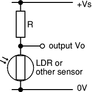
Voltage dividers are widely used in electronics, for example to connect an input transducer such as an LDR to a circuit input.
For successful use the output impedance of the voltage divider should be much smaller than the input impedance of the circuit connected to it.
Ideally the output impedance should be less than a tenth of the input impedance.

In the equivalent circuit of a voltage divider the output impedance is just a resistance and the term 'output resistance' could be used. ROUT is equal to the two resistances (R1 and R2) connected in parallel:
| Output impedance, ROUT = | R1 × R2 | |
| R1 + R2 |
The voltage source VSOURCE in the equivalent circuit is the value of the output voltage Vo when there is nothing connected to the output (and therefore no output current). It is sometimes called the 'open circuit' voltage.
| Voltage source, VSOURCE = | Vs × R2 | |
| R1 + R2 |

Equivalent circuit of a voltage divider
In most voltage dividers one of the resistors will be an input transducer such as an LDR. The transducer's resistance varies and this will make both VSOURCE and ROUT vary too. To check that ROUT is sufficiently low you should work out its highest value which will occur when the transducer has its maximum resistance (this applies wherever the transducer is connected in the voltage divider).
For example: If R1 = 10kΩ and R2 is an LDR with maximum resistance 1MΩ, ROUT = 10k × 1M / (10k + 1M) = 9.9kΩ (say 10kΩ). This means it should be connected to a load or input resistance of at least 100kΩ.

Voltage divider with an LDR
As an Amazon Associate, I earn from qualifying purchases. Any book you purchase through the Amazon links helps to keep this website available for everyone to use free of charge.

This excellent book is widely regarded as essential for anyone wishing to seriously study electronics. Although topics are covered in considerable depth it is written in a relatively easy, informal style with practical examples. Highly recommended.

A great introduction to circuit design with thorough explanations of how the example circuits work.
Next Page: Analogue & Digital | Study