
Pins | Holders | Static | Datasheets | Sink/source | Combine outputs | Logic ICs | PICs
Also see: 555 | 4000 series | 74 series
Integrated Circuits are usually called ICs or chips. They are complex circuits which have been etched onto tiny chips of semiconductor (silicon).
The silicon chip is usually packaged in a plastic holder with pins spaced on a 0.1" (2.54mm) grid which will fit the holes on stripboard and breadboards. Very fine wires inside the package link the chip to the pins.
Surface-mount device (SMD) ICs are designed for machine assembly. They have very short closely-spaced pins and are not suitable for educational or hobby circuits.
The pins are numbered anti-clockwise around the IC (chip) starting near the notch or dot. The diagrams show the numbering for 8-pin and 14-pin ICs, but the principle is the same for all sizes.
Rapid Electronics: ICs (all types)


ICs are easily damaged by heat when soldering and their short pins cannot be protected with a heat sink. Instead we use an IC holder, strictly called a DIL socket (DIL = Dual In-Line), which can be safely soldered onto the circuit board. The IC is pushed into the holder when all soldering is complete.
IC holders are only needed when soldering so they are not used on breadboards.
Rapid Electronics: DIL sockets
If you need to remove an IC it can be gently prised out of the holder with a small flat-blade screwdriver. Carefully lever up each end by inserting the screwdriver blade between the IC and its holder and gently twisting the screwdriver. Take care to start lifting at both ends before you attempt to remove the IC, otherwise you will bend and possibly break the pins.
Commercially produced circuit boards often have ICs soldered directly to the board without an IC holder, usually this is done by a machine which is able to work very quickly. Don't attempt to do this yourself because you are likely to destroy the IC and it will be difficult to remove without damage.
Many ICs are static sensitive and can be damaged when you touch them because your body may have become charged with static electricity, from your clothes for example. Static sensitive ICs will be supplied in antistatic packaging with a warning label and they should be left in this packaging until you are ready to use them.
It is usually adequate to earth your hands by touching a metal water pipe or window frame before handling the IC but for the more sensitive (and expensive!) ICs special equipment is available, including earthed wrist straps and earthed work surfaces. You can make an earthed work surface with a sheet of aluminium kitchen foil and using a crocodile clip to connect the foil to a metal water pipe or window frame with a 10kΩ resistor in series.
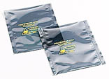
Antistatic bags for ICs
Photograph © Rapid Electronics
Datasheets are available for most ICs giving detailed information about their ratings and functions. In some cases example circuits are shown. The large amount of information with symbols and abbreviations can make datasheets seem overwhelming to a beginner, but they are worth reading as you become more confident because they contain a great deal of useful information for more experienced users designing and testing circuits.
IC outputs are often said to 'sink' or 'source' current. The terms refer to the direction of the current at the IC's output.
If the IC is sinking current it is flowing into the output. This means that a device connected between the positive supply (+Vs) and the IC output will be switched on when the output is low (0V).
If the IC is sourcing current it is flowing out of the output. This means that a device connected between the IC output and the negative supply (0V) will be switched on when the output is high (+Vs).
It is possible to connect two devices to an IC output so that one is on when the output is low and the other is on when the output is high.
The maximum sinking and sourcing currents for an IC output are usually the same but there are some exceptions, for example 74LS TTL logic ICs can sink up to 16mA but only source 2mA.
The outputs of ICs must never be directly connected together. However, diodes can be used to combine two or more digital (high/low) outputs from an IC such as a counter. This can be a useful way of producing simple logic functions without using logic gates!
The diagram shows two ways of combining outputs using diodes. The diodes must be capable of passing the output current. 1N4148 signal diodes are suitable for low current devices such as LEDs.
For example the outputs Q0 - Q9 of a 4017 1-of-10 counter go high in turn. Using diodes to combine the 2nd (Q1) and 4th (Q3) outputs as shown in the bottom diagram will make the LED flash twice followed by a longer gap. The diodes are performing the function of an OR gate.

The 8-pin 555 timer IC is used in many projects. For further information please see the 555 timer page.
Rapid Electronics: NE555 timer
Logic ICs process digital signals and there are many devices, including logic gates, flip-flops, shift registers, counters and display drivers.
Logic ICs can be split into two groups: the 4000 series, and the 74 series which consists of various families such as the 74HC, 74HCT and 74LS.
For most new projects the 74HC family is the best choice. The tables show the supply voltage and maximum output current for each family. The 74LS and 74HCT families require a 5V supply so they are not convenient for battery operation.
Logic IC inputs have high impedances and unused inputs must be connected to 0V or +Vs to avoid erratic behaviour due to inputs switching state in response to stray electrical noise. 74LS ICs are unusual because their inputs 'float' high when unconnected.
The number of logic IC inputs which can be driven by one output of the same family is called the fan out. Usually 50 (10 for 74LS), it is unlikely to matter in simple circuits.
For more details of the logic IC families, including pin arrangements for many ICs, please see these pages:
| Logic IC family | Supply voltage |
| 4000 series | 3 to 15V |
| 74HC | 2 to 6V |
| 74HCT | 5V ±0.5V |
| 74LS | 5V ±0.25V |
| Logic IC family | Maximum output current |
| 4000 series | about 5mA (10mA with 9V supply) |
| 74HC | about 20mA |
| 74HCT | about 20mA |
| 74LS | sink 16mA source 2mA |
| To switch larger currents use a transistor. | |
Rapid Electronics:
4000 series ICs |
74 series ICs
It is best to build a circuit using just one logic family, but if necessary the different families may be mixed providing the power supply is suitable for all of them. For example mixing 4000 and 74HC requires the power supply to be in the range 3 to 6V. A circuit which includes 74LS or 74HCT ICs must have a 5V supply.
A 74LS output cannot reliably drive a 4000 or 74HC input unless a 'pull-up' resistor of 2.2kΩ is connected between the +5V supply and the input to correct the slightly different logic voltage ranges used.
Note that a 4000 series output can drive only one 74LS input.

Driving 4000 or 74HC inputs from a
74LS output using a pull-up resistor.
A PIC is a Programmable Integrated Circuit microcontroller, a 'computer-on-a-chip'. They have a processor and memory to run a program responding to inputs and controlling outputs, so they can easily achieve complex functions which would require several conventional ICs.
Programming a PIC microcontroller may seem daunting to a beginner but there are a number of systems designed to make this easy. The PICAXE system is an excellent example because it uses a standard computer to program (and re-program) the PICs; no specialist equipment is required other than a low-cost download lead. Programs can be written in a simple version of BASIC or using a flowchart. The PICAXE programming software and extensive documentation is available to download free of charge, making the system ideal for education and users at home. For further information (including downloads) see www.picaxe.com
If you think PICs are not for you because you have never written a computer program, please look at the PICAXE system. It is very easy to get started using a few simple BASIC commands and there are a number of projects available as kits which are ideal for beginners.
Rapid Electronics: PICAXE
Rapid Electronics have kindly allowed me to use their images on this website and I am very grateful for their support. They stock a wide range of ICs and other components for electronics and I am happy to recommend them as a supplier.
As an Amazon Associate, I earn from qualifying purchases. Any book you purchase through the Amazon links helps to keep this website available for everyone to use free of charge.
Next page: 4000 series ICs